Internship project: Nassim - Bio-Inspired Systems team, Institut des Sciences du Mouvement. Design, fabrication, textile reinforcement and instrumentation of a pneumatic demonstrator reproducing stomatal opening.
Internship project: Nassim
Supervisor: Loïc TADRIST
Team: Bio-Inspired Systems (SBI)
Laboratory: Institut des Sciences du Mouvement (ISM)
Topics: stomate, guard cell, Ecoflex molding, anisotropic reinforcement and instrumentation
How can the opening movement of a stomate be reproduced at a macroscopic scale?
The project focuses on the design and fabrication of a bio-inspired educational demonstrator. Two pneumatic guard cells made of Ecoflex and reinforced with textile fibers reproduce the visible opening of a stomate.
1. Project objective
The internship focuses on the design and fabrication of a teaching demonstrator that reproduces the opening mechanism of a stomate at a macroscopic scale. The demonstrator is intended for scientific outreach and must make the movement of two guard cells visible and understandable.
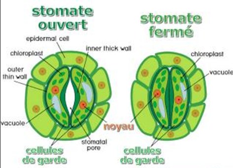
Biological diagram of a stomate
A stomate is made of a pore, called the ostiole, surrounded by two guard cells. These guard cells regulate gas exchange and water loss in the plant.
2. Biological principle reproduced
In a plant, guard cells become turgid when they fill with water. Their inner wall is more rigid than their outer wall, which causes the cells to bend and open the ostiole. The demonstrator reproduces this principle with a soft pneumatic structure that inflates and bends in a controlled way.
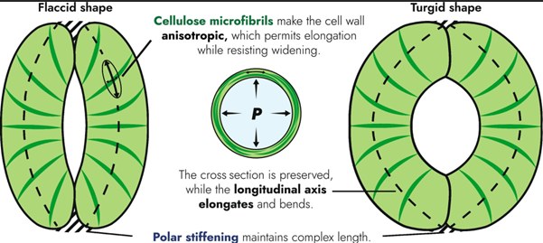
Anisotropy of the guard cells
The movement of the stomate depends on directional stiffness. This anisotropy is reproduced by reinforcing the elastomer with textile fibers.
3. First CAD version of the demonstrator
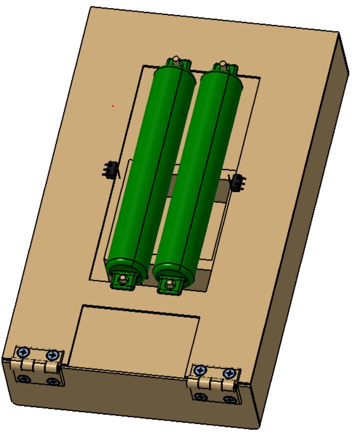
A first rough CAD model was produced to define the global organization of the demonstrator. The guard cells are held above a base, the humidity sensor is placed near a sponge reservoir and the limit switches are positioned on the sides. This first model helped identify the components needed before improving the mechanical design.
First CAD version of the stomate demonstrator
Initial CAD view of the demonstrator with two guard cells, a support plate and the planned positions of the sensors and pneumatic elements.
4. Pneumatic actuation choice
A pneumatic system was selected to reproduce guard-cell swelling. The goal is not to copy the exact hydraulic process of a plant, but to create a clean, low-cost and safe way to pressurize the soft cells for a visible demonstration.
5. Functional requirements
The main requirement is to make the opening of the ostiole visible to the naked eye, with two guard cells and an opening width of around 20 mm. The demonstrator must also remain easy to use, ready quickly, supplied with low control voltages and protected against excessive pressure.
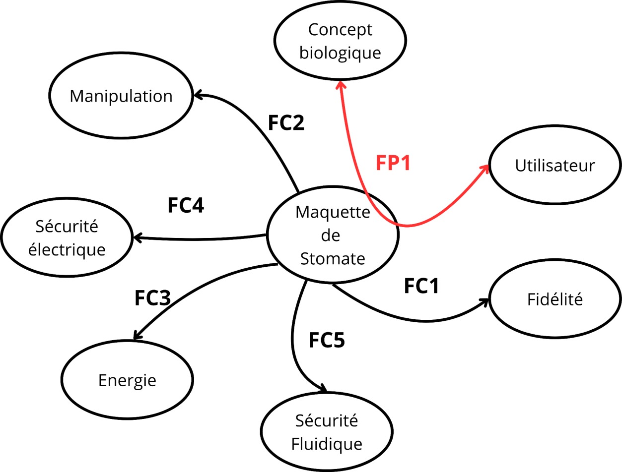
Object-interaction diagram of the demonstrator
The functional diagram links the biological concept, the user, the energy supply, manipulation, fidelity, electrical safety and pneumatic safety.
6. Mold design and 3D printing
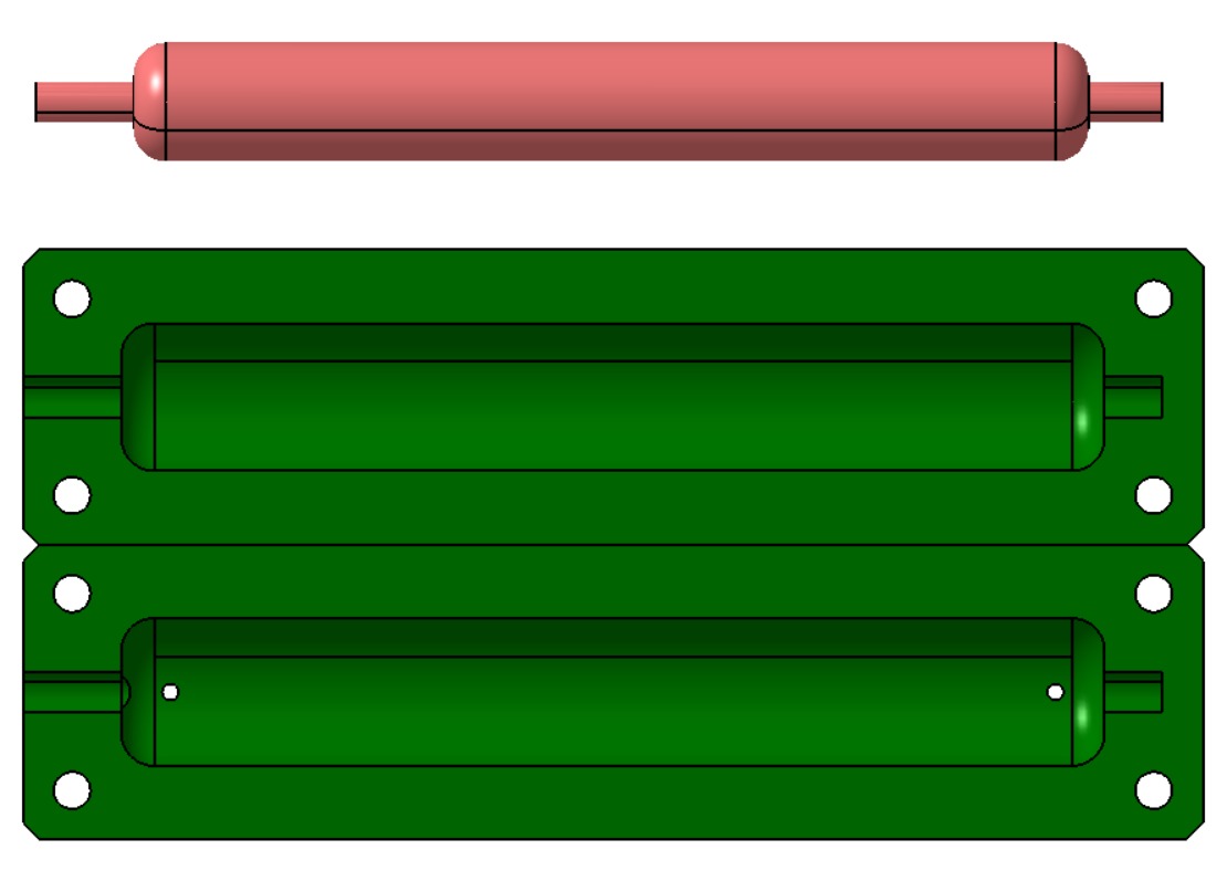
The guard cells cannot be bought directly as anisotropic elastomer tubes, so they are manufactured with molds. The molds are designed in two parts with a central core. They are printed in PLA with a fine layer height to obtain a smoother surface and preserve the curved geometry.
CAD design of the guard-cell molds
CAD model of the guard-cell mold, the core and the two mold halves. The injection hole and the rounded edges help the molding process.
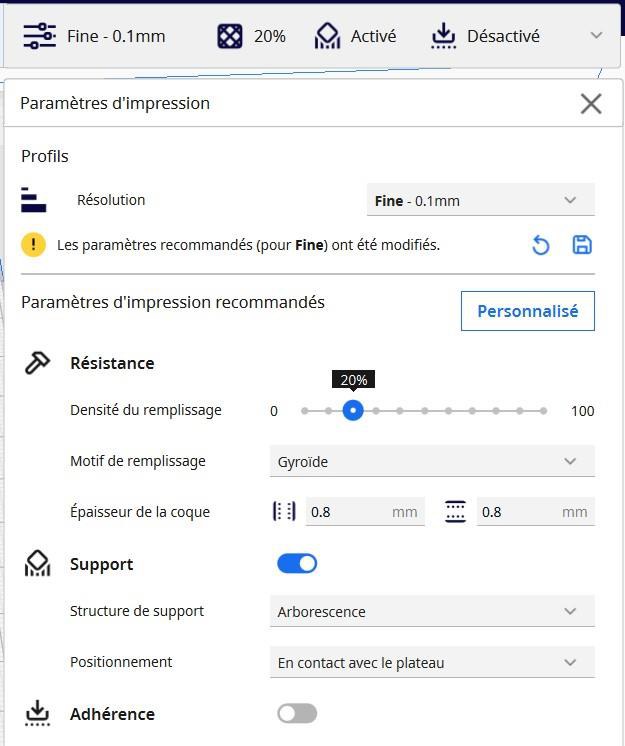
Mold printing parameters
The print settings are chosen to obtain accurate molds with a good surface finish for Ecoflex casting.
7. Ecoflex molding process
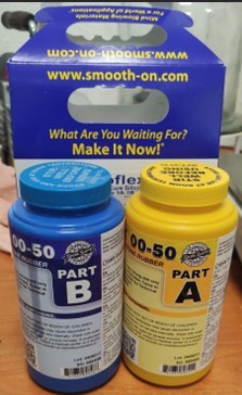
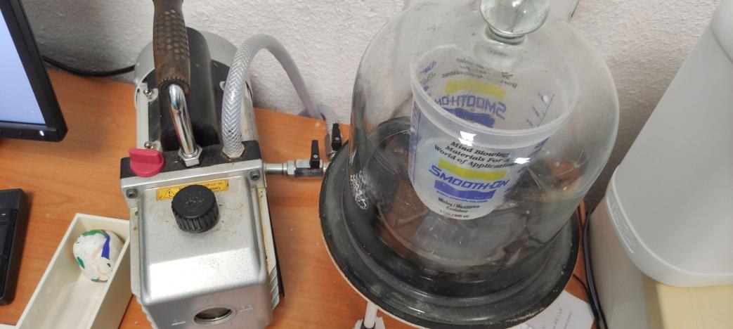
The guard cells are cast with Ecoflex 00-50. The two parts of the silicone are mixed in a 1:1 ratio, degassed under vacuum, injected into the mold and left to cure. Several trials were required to reduce bubbles, improve sealing and obtain complete parts.
Ecoflex 00-50 used for molding
The silicone is mixed from two components before being degassed and injected into the mold.
Vacuum degassing
Degassing reduces bubbles in the silicone before or during the molding sequence.
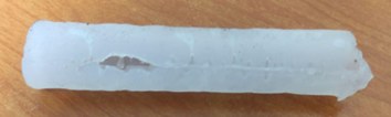
First incomplete guard-cell trial
Early trials showed missing material, bubbles and holes. These defects guided the improvement of the injection and venting method.
First successfully formed guard cell
After improving clamping and injection, a complete guard cell could be obtained and removed from the mold.
8. Fiber reinforcement and anisotropy
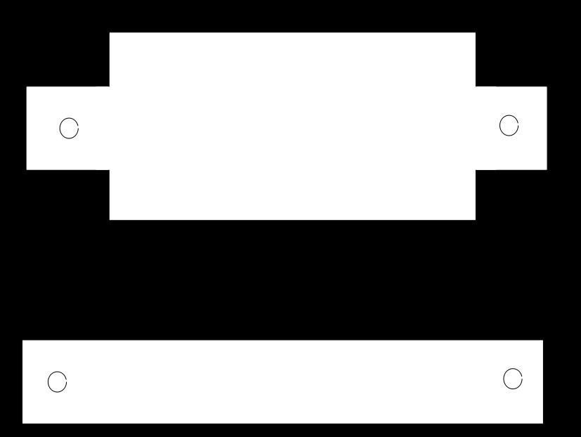
The movement depends on a stiffness difference between directions. Textile reinforcement is therefore added to the Ecoflex guard cell. The fabric is impregnated with silicone, positioned around the cell and used to reproduce the anisotropic behavior of the biological wall.
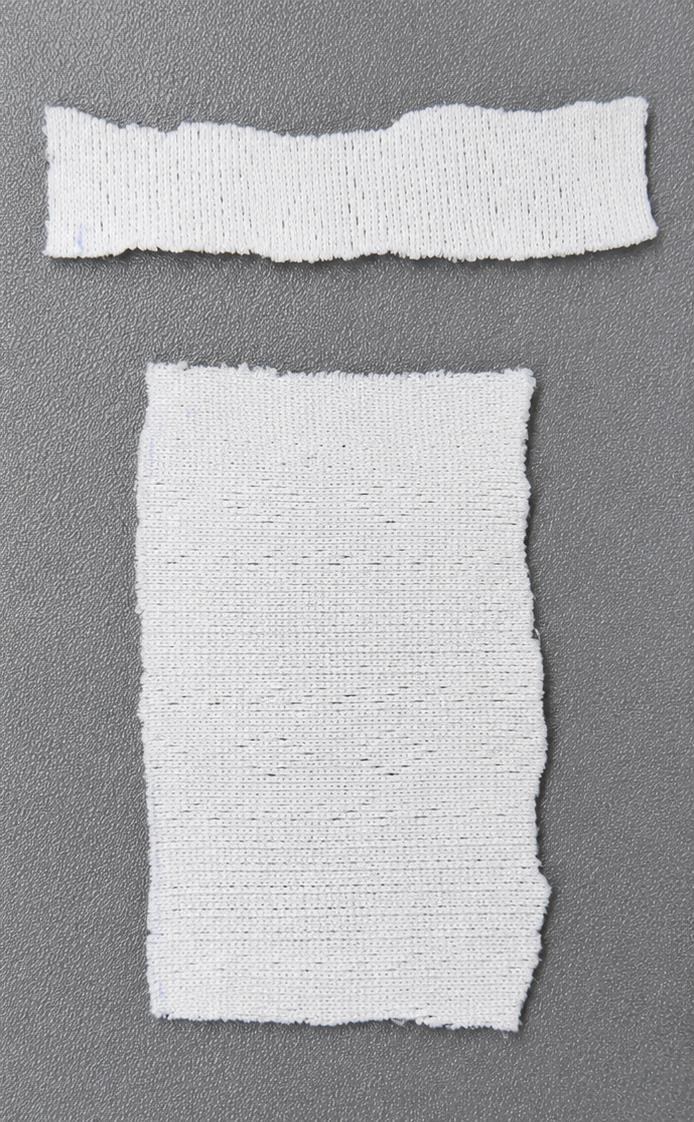
Textile reinforcements used for fiber wrapping
The textile pieces are cut, impregnated with Ecoflex and positioned around the guard cell to modify stiffness.
Fiber-wrapping patterns
The patterns help place the fabric more repeatably around the guard cell and improve the bending behavior.
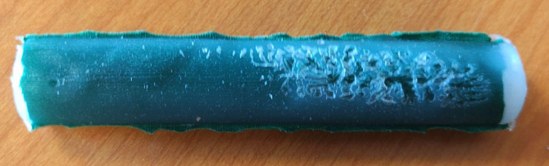
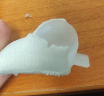
Failure during pressure testing
Some trials ruptured when the wall thickness or fiber placement was not sufficient. These failures helped identify the correct reinforcement strategy.
9. Iterative results
More than thirty trials were carried out to understand the molding and reinforcement parameters. The final method uses successive molds and a controlled fiber layout to obtain functional guard cells with improved repeatability.
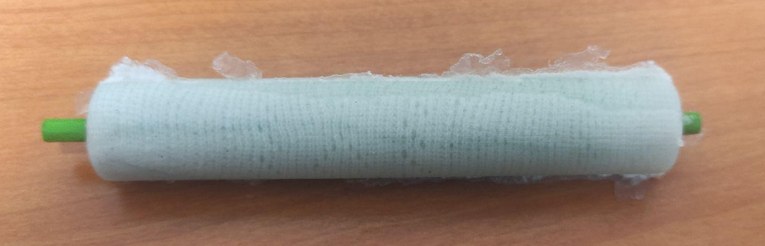
Final fiber-reinforced pneumatic guard cell
The final reinforced guard cell bends under pressure thanks to directional stiffness created by the textile reinforcement.
Mounted pair of guard cells
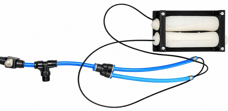
The two guard cells are fixed to a rigid support plate and connected to the pneumatic circuit to form the macroscopic stomate demonstrator.
10. Instrumentation
The demonstrator is instrumented with limit switches, humidity sensors and a pressure sensor. These components make it possible to monitor the system, characterize the pneumatic response and prepare future automated experiments.
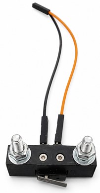
Limit switch sensor
The limit switches detect mechanical positions on the demonstrator and help monitor movement.
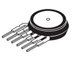
MPX5999D pressure sensor
The pressure sensor is used to measure the pneumatic pressure applied to the guard cells. The selected range covers the pressures required during the tests.
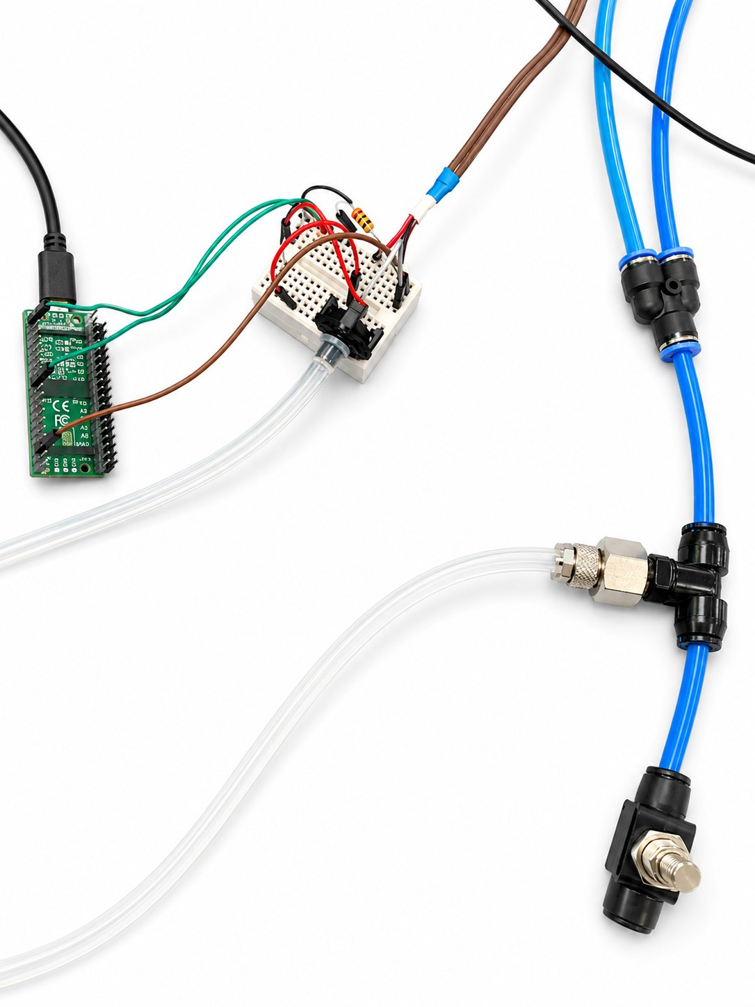
Electrical and pneumatic acquisition setup
Real electrical and pneumatic assembly used to acquire pressure measurements during tests.
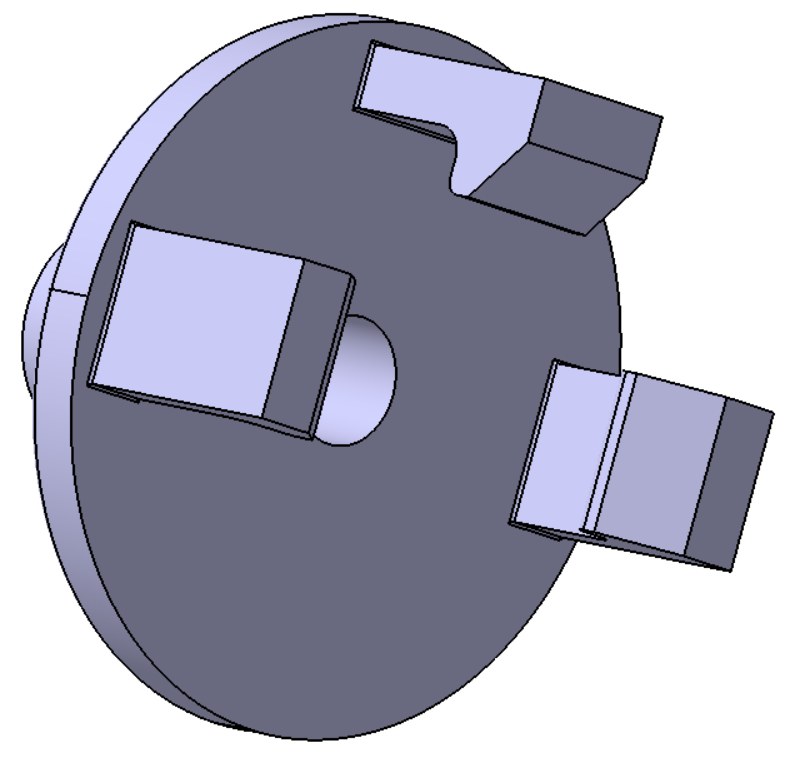
Pressure-sensor snap-fit CAD
The snap-fit part clips the pressure sensor and connects it to the pneumatic tube. It is printed in PLA.
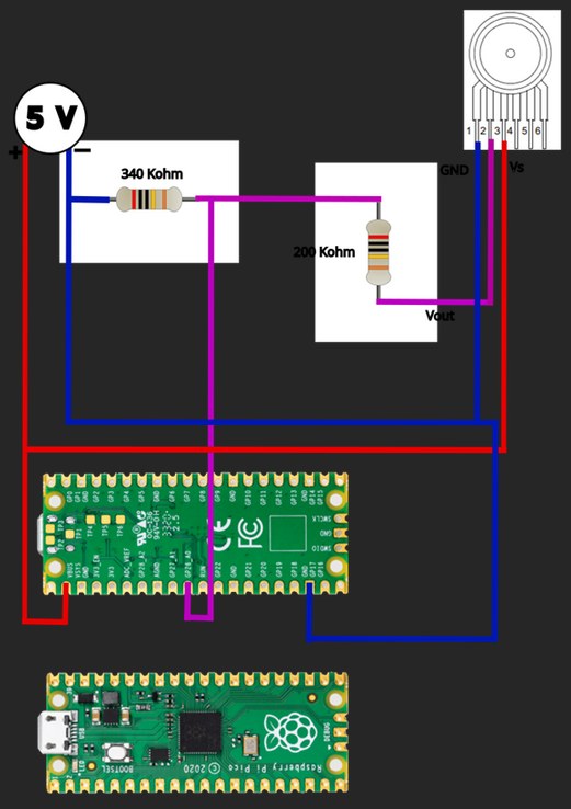
Pressure-sensor wiring diagram
The sensor is supplied at 5 V and its output is adapted to the Raspberry Pi Pico input using a voltage divider.
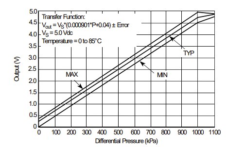
Pressure transfer curve
The sensor output voltage is converted into pressure using the transfer relationship from the datasheet.
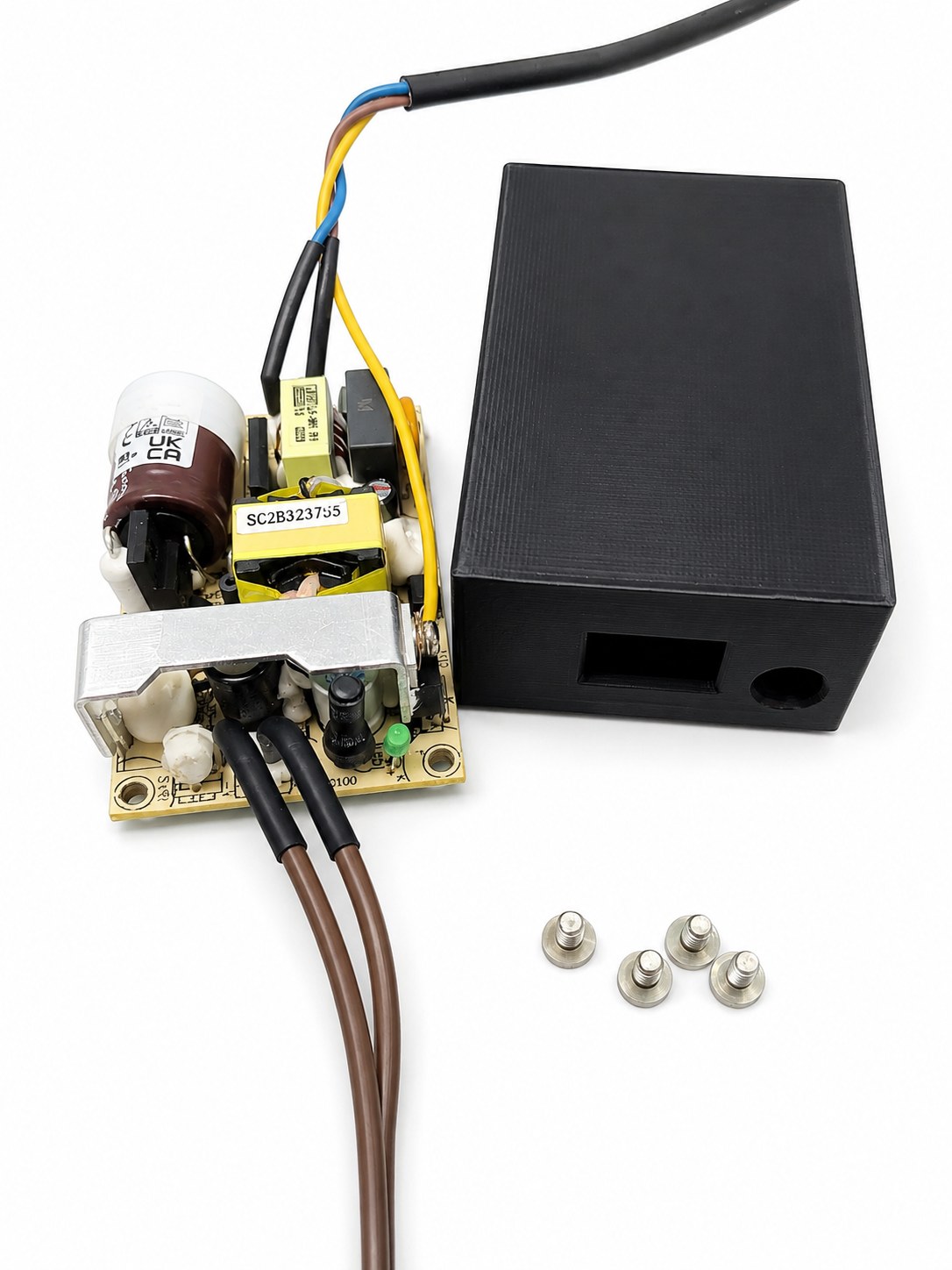
5 V power-supply enclosure
A dedicated enclosure was designed to make the 5 V pressure-sensor supply safer and cleaner for the demonstrator.
11. Pressure measurements
Tests showed that around 80 kPa are needed to inflate the guard cells sufficiently, around 100 kPa are needed to obtain opening, and 120 kPa must not be exceeded because the cells can be damaged.
MicroPython: main demonstrator program
Main program grouping limit-switch monitoring, DHT11 humidity readings and analog pressure acquisition.
from machine import ADC, Pinimport time# --- CONFIGURATION DU CAPTEUR DE PRESSION NXP ---capteur_pression = ADC(Pin(26)) # Connecté sur GP26 (ADC0)V_S = 3.15 # Votre tension de référence réelle (VS)ADC_MAX = 65535print(f"Lecture en temps réel avec la formule P = ((Vout/VS) - 0.04) / 0.09")print("-" * 55)while True: try: # 1. Lecture de la valeur brute (0 à 65535) valeur_brute = capteur_pression.read_u16() # 2. Calcul de Vout (la tension lue par le Pico entre 0 et 3.15V) v_out = (valeur_brute / ADC_MAX) * V_S # 3. Application de votre formule pour trouver P (en kPa) pression_kpa = ((v_out / V_S) - 0.04) / 0.000901 # Sécurité pour éviter le bruit électrique négatif quand la pression est nulle if pression_kpa < 0: pression_kpa = 0.0 # Conversion en Pascals (Pa) pour afficher les petites variations pression_pa = pression_kpa * 1000 # 4. Affichage des résultats dans la console Thonny print(f"Vout: {v_out:.3f}V | Pression: {pression_kpa:.3f} kPa ({pression_pa:.1f} Pa)") except OSError: print("Erreur de lecture du capteur.") # Pause de 0,5 seconde entre chaque mesure time.sleep(0.5)
MicroPython: humidity sensors
DHT11 sensor script used to read humidity and temperature around the demonstrator.
from machine import Pinimport dhtfrom time import sleep# Configuration des deux capteurs DHT (ici en version DHT11)capteur1 = dht.DHT11(Pin(1)) # Connecté sur GP1capteur2 = dht.DHT11(Pin(10)) # Connecté sur GP2print("Lecture des deux capteurs (Humidité et Température)...")while True: try: # On déclenche la mesure pour les deux capteurs capteur1.measure() capteur2.measure() # Récupération de l'humidité et de la température humi1 = capteur1.humidity() temp1 = capteur1.temperature() humi2 = capteur2.humidity() temp2 = capteur2.temperature() # Calcul des différences absolues diff_humidite = abs(humi1 - humi2) diff_temperature = abs(temp1 - temp2) # Affichage des valeurs brutes print(f"Capteur 1 -> Temp: {temp1}°C | Humidité: {humi1}%") print(f"Capteur 2 -> Temp: {temp2}°C | Humidité: {humi2}%") # Affichage des écarts print(f"--> Écart de Température: {diff_temperature}°C") print(f"--> Écart d'Humidité: {diff_humidite}%") print("-" * 40) # Ligne de séparation pour lisibilité except OSError as e: print("Erreur de lecture sur l'un des capteurs. Vérifiez les branchements.") # Pause de 2 secondes avant la prochaine mesure sleep(0.5)
MicroPython: limit switches
Script used to test and monitor the limit switches installed on the demonstrator.
from machine import Pinimport time# Configuration des deux capteurs avec Pull-Up internefde_bas = Pin(11, Pin.IN, Pin.PULL_UP) # Capteur Début / Bas sur GP14fde_haut = Pin(9, Pin.IN, Pin.PULL_UP) # Capteur Fin / Haut sur GP15print("Surveillance des deux fins de course active...")while True: # Vérification du capteur Bas (0 = enfoncé) if fde_bas.value() == 0: print("Alerte : Position MINIMUM Gauche atteinte !") # Insérez ici l'action (ex: stopper le moteur, changer de direction) time.sleep(0.2) # Anti-rebond # Vérification du capteur Haut (0 = enfoncé) if fde_haut.value() == 0: print("Alerte : Position MAXIMUM Droite atteinte !") # Insérez ici l'action (ex: stopper le moteur) time.sleep(0.2) # Anti-rebond time.sleep(0.05) # Lecture rapide pour ne rater aucun clic
MicroPython: electrovalve control
Script used to control the electrovalve during pneumatic tests. The obsolete automatic pump-regulation section was removed from the page.
from machine import ADC, Pinimport time# --- CONFIGURATION DE L'ÉLECTROVANNE (RELAIS) ---# Connectée sur GP5# 1 = Vanne fermée (relais repos) | 0 = Vanne ouverte (relais actif)electrovanne = Pin(5, Pin.OUT)electrovanne.value(1) # Fermée par défaut au démarrage# --- CONFIGURATION DU CAPTEUR DE PRESSION ---capteur_pression = ADC(Pin(26)) V_S = 3.15 # Tension de référence réelle (VS)ADC_MAX = 65535# --- VALEUR CIBLE (À MODIFIER SELON VOS BESOINS) ---CONSIGNE_BAR = 0.3 # Pression cibleprint("-" * 60)print(f"Contrôle Électrovanne - Cible fixe : {CONSIGNE_BAR:.2f} bar")print("Maintien fermé pendant 30s avec affichage de la pression en temps réel.")print("-" * 60)while True: try: # 1. Lecture du capteur et calcul de la pression en bar valeur_brute = capteur_pression.read_u16() v_out = (valeur_brute / ADC_MAX) * V_S pression_kpa = ((v_out / V_S) - 0.04) / 0.000901 if pression_kpa < 0: pression_kpa = 0.0 pression_bar = pression_kpa / 100.0 # --- LOGIQUE DE L'ÉLECTROVANNE --- if pression_bar < CONSIGNE_BAR: electrovanne.value(0) # Ouvre la vanne print(f"Pression Réelle: {pression_bar:.2f} bar | Électrovanne: OUVERTE (Remplissage)") time.sleep(0.5) # Pause classique entre deux mesures de remplissage else: # La cible est atteinte : on ferme immédiatement electrovanne.value(1) print(f"Pression Réelle: {pression_bar:.2f} bar | Électrovanne: FERMÉE (Cible atteinte !)") print(">>> Début du maintien de 30 secondes <<<") # Boucle de 30 secondes qui lit le capteur en temps réel for seconde_restante in range(30, 0, -1): # On reprend une mesure fraîche du capteur pendant la pause valeur_brute = capteur_pression.read_u16() v_out = (valeur_brute / ADC_MAX) * V_S pression_kpa = ((v_out / V_S) - 0.04) / 0.000901 if pression_kpa < 0: pression_kpa = 0.0 pression_bar_pause = pression_kpa / 100.0 # Affichage en temps réel du décompte ET de la pression actuelle print(f"[MAINTIEN] Temps restant: {seconde_restante}s | Pression actuelle: {pression_bar_pause:.2f} bar | Électrovanne: FERMÉE") time.sleep(1.0) print(">>> Fin du maintien. Reprise de la régulation standard. <<<\n") except OSError: print("Erreur capteur. Sécurité : Fermeture de la vanne.") electrovanne.value(1) time.sleep(0.5)
12. CAD archive and technical files
The CAD archive contains the technical design files of the stomate demonstrator, including the guard-cell molds, mechanical supports, sensor holders, enclosure parts and assembly files. It is kept as a downloadable archive while selected STL parts are also previewed directly on the page.
Download the stomate CAD archive
Downloadable archive containing the CAD and technical files of the stomate teaching demonstrator.
Representative STL files were extracted so they can be previewed directly in 3D. The full CAD archive remains available for all CATIA and technical files.
STL file available in the web version of the project.
13. Perspectives
The next step is to finalize the full integration of the pneumatic and electronic system. The report also highlights that sealing, homogeneous inflation and edge ruptures remain important points for future improvement.
Download this project page
Use this button to open the print dialog, then choose “Save as PDF”.